Crossing Oceans in Small Craft

This is a two-part exploration that is based on a craze within the boating community from a few years ago in which, otherwise sane folks looked to cross a major ocean in ever-smaller boats to set some kind of record

The first part of this kooky, tongue in cheek journey involves the use of medical high-tech tomfoolery. I call this design the Stasis 7. The second part of our academic adventure involves a “boat” that actually has a quite a bit of potential in its design thinking and even if it engages a good bit of nuttiness in some of its appendage magnificence, it could still work effectively. I call that one, The Oceanic Pencil.

These two articles were published some time ago on Duckworks and they drew quite a bit of reader response back then. In this day and age, with advancements in medical capabilities, enhanced technology in all disciplines and a solid understanding of solar and wind electrical generation systems, these kinds of projects are just simmering, waiting for someone to come along who really wants to to push the boundaries and benefit from the data so discovered along the way.

Please sit down, kick back and digest the goofy, the real, the possible ways for one to get oneself across a major body of water and do so in a couple of ways that nobody is currently considering.

STASIS7
Initial Concept for Trans-Oceanic Smallness

design by Chris Ostlind

Stasis-profile-w

Nope, this time it was all about how small can you get it and still cross an ocean. Personally, I find this process to be right out of the tales of Marquis deSade, as only a true masochist would fold himself into one of these ridiculous compartments and call it comfortable for anything more than a Photo Op.

Dr. Phil couldn’t have suited-up a better guest for his show than this.Nevertheless, there it was, the announcement that someone was going to not only build one of these claustrophobia generators, but they were also going to do a booklet on the construction of same… and have the audacity to charge for said, copyrighted booklet.

So there I sat in my studio, wondering just what went into the decision making process that would lure an apparently sane person into the interior of what amounts to a floating sleeping bag for a trans-oceanic thrash into some level of personal stardom.

Hmmmmm, the mind can truly do some weird things when it gets onto a roll of such obscure strategies.

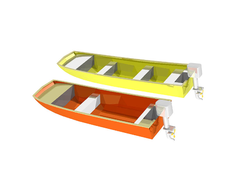
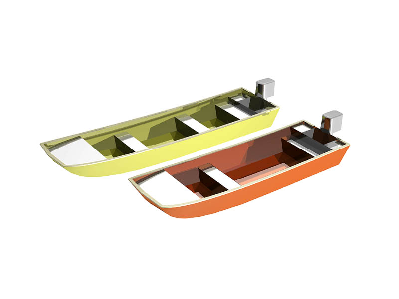
OK, I’ll just admit it up front. The weirdness (some might call it macabre) of it all had me hooked and so I set off to design a pair of really small boats for tooling off into the sunrise after leaving the safety of Newfoundland. Great Britain, here I come, though not without my own philosophical baggage along with a whole host of ethical questions regarding ocean crossing behaviors. This is the first of the two designs.

Stasis7-Bow-enclosed-w

I believe that my design for the boat I call Stasis7 does that and more.While the current record for the smallest boat to sail across an ocean is held by the 5’4” Father’s Day sailed by Hugo Vihlen, I wasn’t really going for the record with my first design. Instead, I wanted scientific novelty and the undying adoration of the pharmaceutical and medical community. I also wanted to take the tiny boat community and functionally poke it in the eye…. repeatedly.

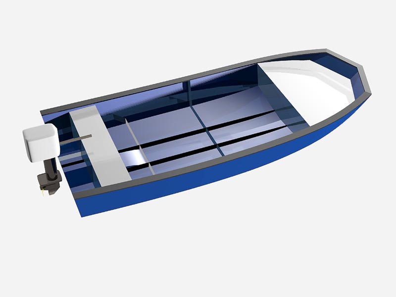
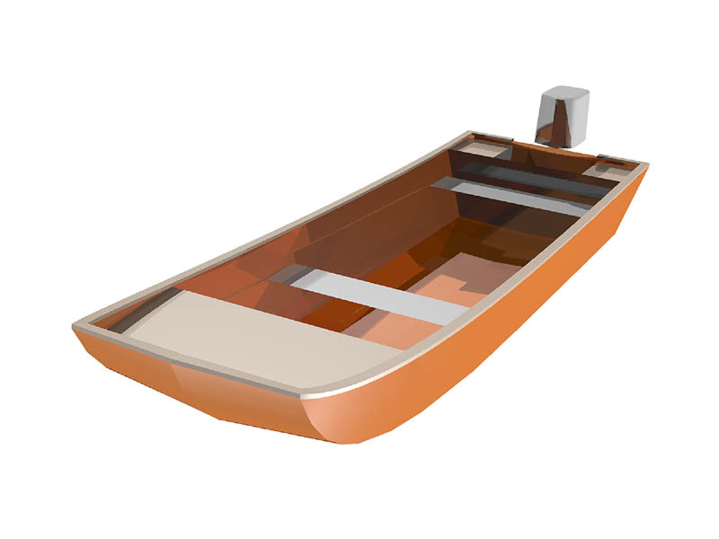
The big issues aboard such a small boat are, naturally where to store the necessary food and water as well as how to keep the crew safe in nasty conditions. Stasis7 addresses those concerns with a novel set of solutions that virtually guarantee a healthy and rested crew upon arrival in Great Britain, though they may just be regarded as cadaverous by any normal measuring method.

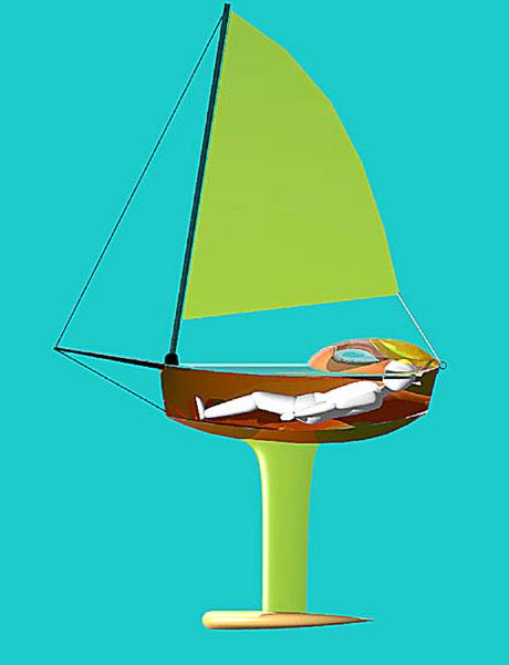
The boat is a mere 7’ in length overall with a beam of just 32”. Stasis sports a sail of just under 30 sq. ft. The sail mounts to an aft pivoting step right at the stem with a small bowsprit projecting forward from nearly the same position. The sail is fixed to the mast and the mast rotates to reef the sail. In a big blow the mast not only rotates to stow the sail but it lays flat on the deck.

Stasis-Aft-1-w

All sail controls are automated from a central microprocessor that takes input from wind speed and direction, barometric pressure, sea state differential potentiometers, G-force sensors and GPS. The sensor output is collected and fed through the processor where it is compared to hundreds of different sailing and sea state scenarios to predict conditions, as well as derive the proper settings of sail trim and deployed surface presented to the wind. In short, all sailing controls are automated for the occupant.

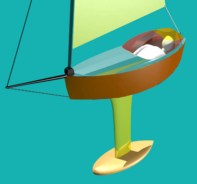
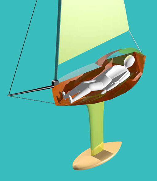
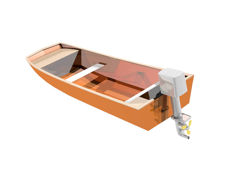
At the core of the success of the boat is it’s fantastic ultimate stability which is derived from a long, hollow keel appendage that is terminated with a weighted bulb that is cast in one piece, guaranteeing that the bulb will not fall off, destabilizing the boat while under way.

The long, fin appendage also houses all the necessary life support equipment for the journey, thus freeing-up the cabin space in the main hull for the crew’s comfort. Crew comfort in this case, is perhaps a misnomer of sorts, as it is not derived in the normal sense of the descriptive usually associated with boating activities.
Stasis7-Bow-ECU-wThe solo crew of Stasis7 will cross the Atlantic in a drug-induced state of suspended animation.

To truly free the occupant from most of the needs of the typical metabolizing human, they will be hooked-up to an I.V. drip for the entire journey. The IV solution will provide the minimum amounts of saline, sucrose and necessary salts to maintain proper metabolic conditions while under the influence of the proprietary Stasis7 cocktail that is included in the solution.

The crew will wear a special suit that will recycle all fluid perspiration and return it to the filtering system where it will be made available for re-introduction to the IV process. The same will apply to all urine, as it will be collected via catheter for the same, recycling process.

With metabolic rates reduced to less than 10% of the normal, resting condition, supplemental needs will be reduced to near zero beyond those provided in the IV.

Stasis7-Bow-w

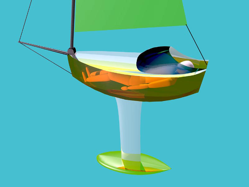
Mild brain stimulation will be provided through a special skullcap that will massage the electric capacity of the brain to keep the synapses firing at a very low ebb. This will ensure that the crew can come back out of the Stasis process as the craft nears the shores of England.

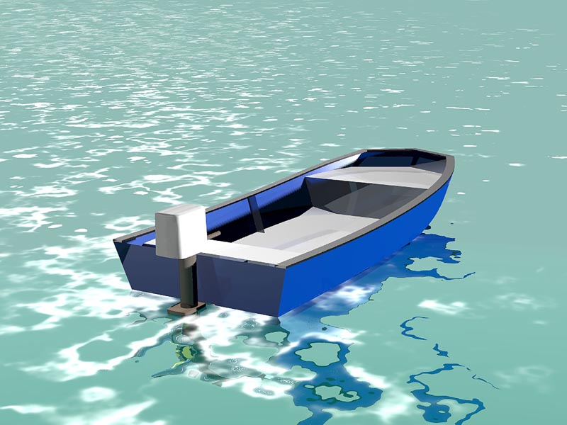
Since this boat is designed to take a small advantage from the prevailing winds during the journey, it is primarily a drifting vehicle that will enjoy the gifts of the Gulf Stream for most of the trip.

It’s a simple boat, really. A comfortably padded interior with soft, NASA memory foam throughout. A smart glass, Lexan, canopy that darkens in bright light and returns to a nearly clear state in the night, will regulate lighting.

So, there it is; the no-brainer method to cross an ocean in the smallest of boats with minimal hassle for the occupant. At thirty miles off the English Coast, the GPS triggers an automatic injection into the IV solution of a pleasant chemical cocktail that brings the crew back to a normal state. This process allows them to steer the Stasis7 into the nearest harbor for a pre-placed meal, designed to jump-start their GI tract without any rude surprises.

click to enlargeI figure 2 months and some change to get across the Atlantic.

Chris Ostlind
Lunada Design


OCEANIC PENCIL
Second Design for Trans-Oceanic Smallness

design by Chris Ostlind

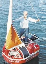
I was looking hard at the various tiny boats that have crossed the Atlantic over the years and they seem to have gotten smaller to the point of the absurd. I previously mentioned Hugo Vihlen’s record setting boat, Father’s Day at 5’4” from 1993. It was pretty obvious to me that his boat had been measured to 5’4” in order to just whisker under the boat length of his ultra-micro crossing rival, Tom MacNally who had just performed the same feat in his boat, Vera Hugh, that was 5’4.5”, also in 1993.


2008-09-22_8155_bigc

MacNally rallied his forces to produce an even shorter boat in 1998, the Vera Hugh II that measured an astoundingly short 3’11” for a go at the record. Apparently that boat did make the journey from Portugal to the Canaries, but for some reason, has not actually been put in the water for the big jump across the Atlantic to the Caribbean. As far as I know, she still sits in storage in the Canaries, waiting for her suitor to ride her to victory.


That means the door is wide open for a memorable, record setting design to splash down off Labrador and be swept to the enchanting Isles of Great Britain in the loving arms of the Gulf Stream.

Coincidentally, I have just the design to do both tasks, though it does require a bit of creative interpretation of the apparent rules in order to truly get a boat down to those sizes for this trip.

When you look at the Vera Hugh II in photos, what you see is essentially a floating, untethered buoy that has a very small sail area to augment its drifting posture at sea. The boat is festooned with bolted or welded-on apparatus to further enhance the capabilities while leaving the essential hull length undisturbed. Apparently, this festooning includes the rudder and the support tubing to hold it aft and stable. If the loose interpretation allows for such a craft to be measured by the contained vessel volume alone, then I’m in there with my new design.

OP-Damped-High-Tight-w


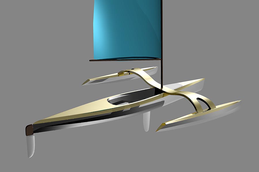
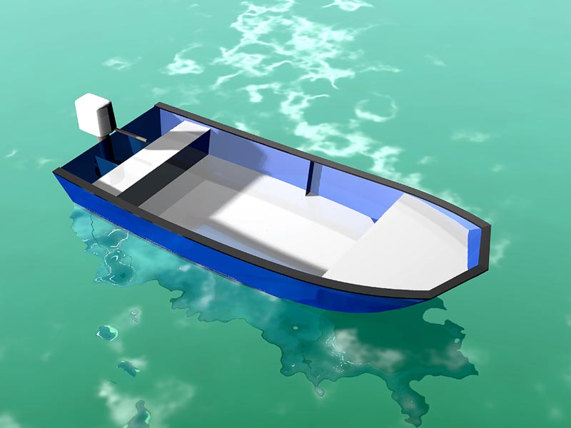
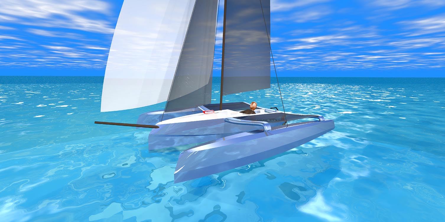
I present the Oceanic Pencil, a craft made for the purpose of long distance, ocean crossing sailing/drifting/kiting while performing valuable scientific studies of the currents, flora and fauna, salinity issues and water temps along the way.


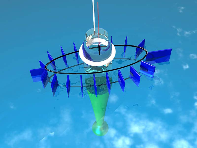
The Pencil’s in-the-water length, is 5’ exactly. That was easy to arrive at because the “boat” is pretty much just a cylinder that has been put up on its end. I can easily take the title of smallest boat at 5’ and only the Vera Hugh II, sitting in dry dock has any chance of breaking the record that the Oceanic Pencil will hold. The fact that I will liberally decorate the Pencil’s topsides with all manner of geometrically welded aluminum tubing is well within accepted norms for boats of this type.

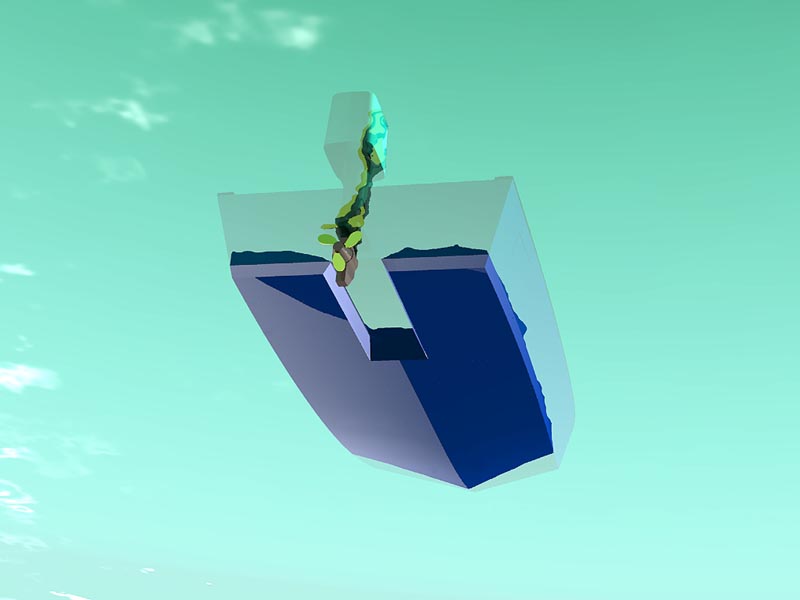
The cylinder is kept in the up and down position by means of a suspended bulb keel. Actually, the cylinder tapers over its lower half until it reaches the bulb some ten feet below the living quarters area. I have designed the bulb to be filled with depleted uranium bullets and recovered shrapnel from the Iraqi conflict. The uranium’s radioactivity is shielded from the Pencil’s occupant with a liberal casing of pure lead. So, the problem of ballast is solved, and the world is better for it.

A lot of additional life support systems are also stored as low as possible in the keel appendage and also the bulb such as heavy stores and batteries for the on-board electronics systems.

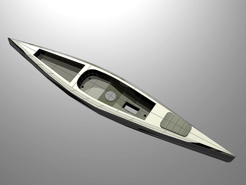
Working our way up the keel cone, the Pencil maintains a series of low profile, rack mount computers for all the scientific functions that will be performed en route. The upper reaches of the cone provide space internally for ladder-climbing exercise routines for the crew to keep them fit. Unlike the Stasis 7, I don’t want my Pencil sailor to slowly turn to atrophied jelly while he crosses the open sea.

In the upper, cylindrical environment of the Pencil, the space has been given over to the comforts of the sailor with retractable video screens to monitor all the science functions as well as accurately chart the movement of the boat through the sea. This includes depth sounders, sonar, radar, military accurate GPS, several direct communications systems as well as full Internet connections in the Gigabyte speed region and on-board entertainment capabilities to pass the time when not engaged with his science duties.

OP-Folded-Tight-w

Sleeping on board the Pencil is done through a suspended hammock device that can be adjusted through several control points. This gives maximum comfort at the same time allowing the crew to infinitely adjust the attitude of the hammock for best resting position.

The upper four feet of the cylinder is actually composed of heavy gauge Lexan to give a full 360 degree view out to the surface interface so that the crew may observe sea life directly during daylight and also at night augmented with the use of waterproof high intensity lighting.

The cap of the cylinder is capable of being flipped open during calm conditions, but can be securely dogged-down for the periods of time when the boat is being subjected to dramatic sea state conditions. Antennas for most of the communication systems and GPS are mounted to the roof of the flip open hatch. Some are mounted to the ring around the hatch so that they remain in their optimal, vertical orientation for continuous communication while the hatch is open.

Perhaps the most interesting survival feature for these wild conditions is the fact that the boat can be re-positioned vertically in the water column. In short, the crew can take-on additional water ballast and literally sink the Oceanic Pencil to a controlled depth that takes away virtually all of the surface disturbances from the motion of the boat. When the storm has passed, the boat blows the ballast tanks with compressed air and returns to the surface.

OP-Folded-Kite-w

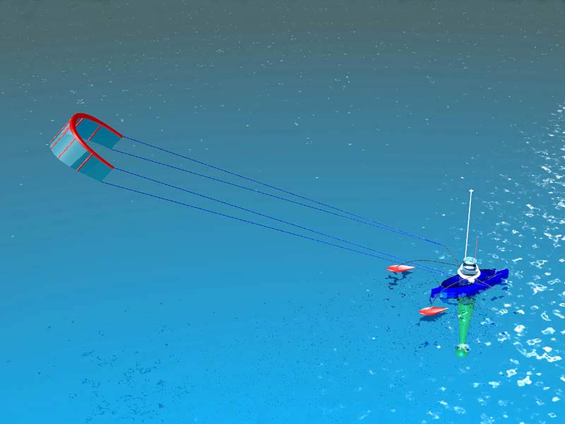
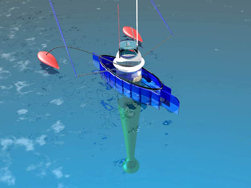
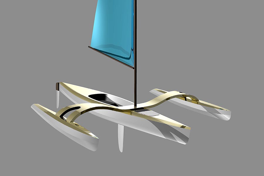
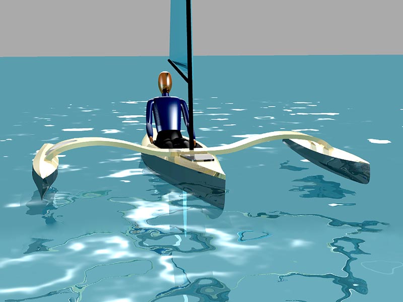
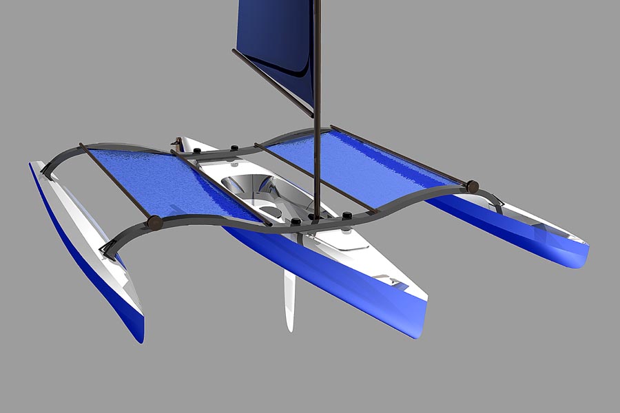
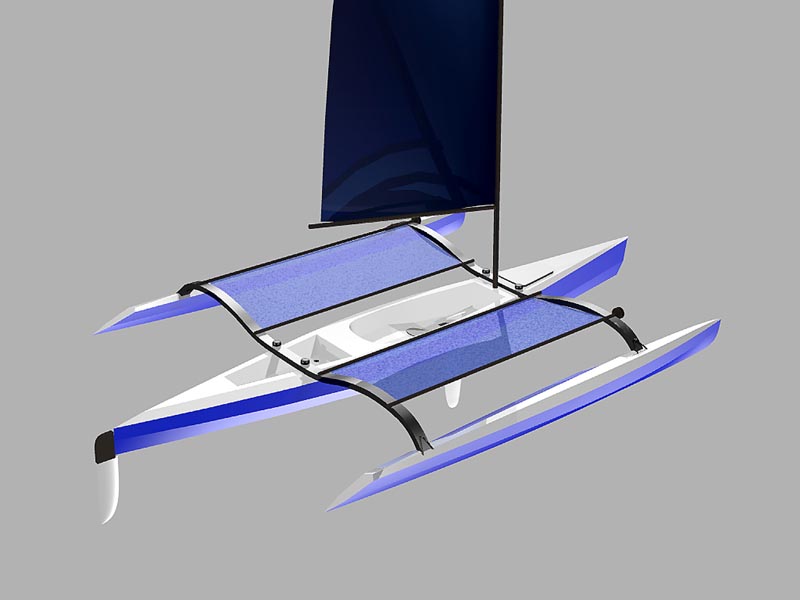
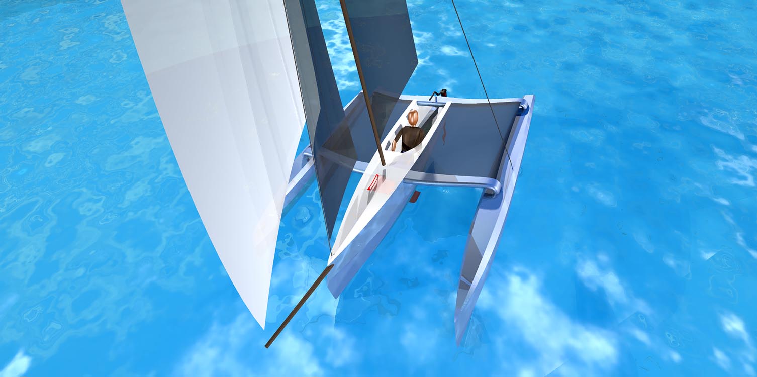
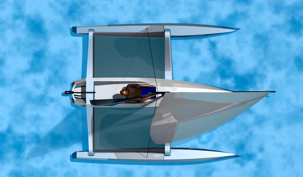
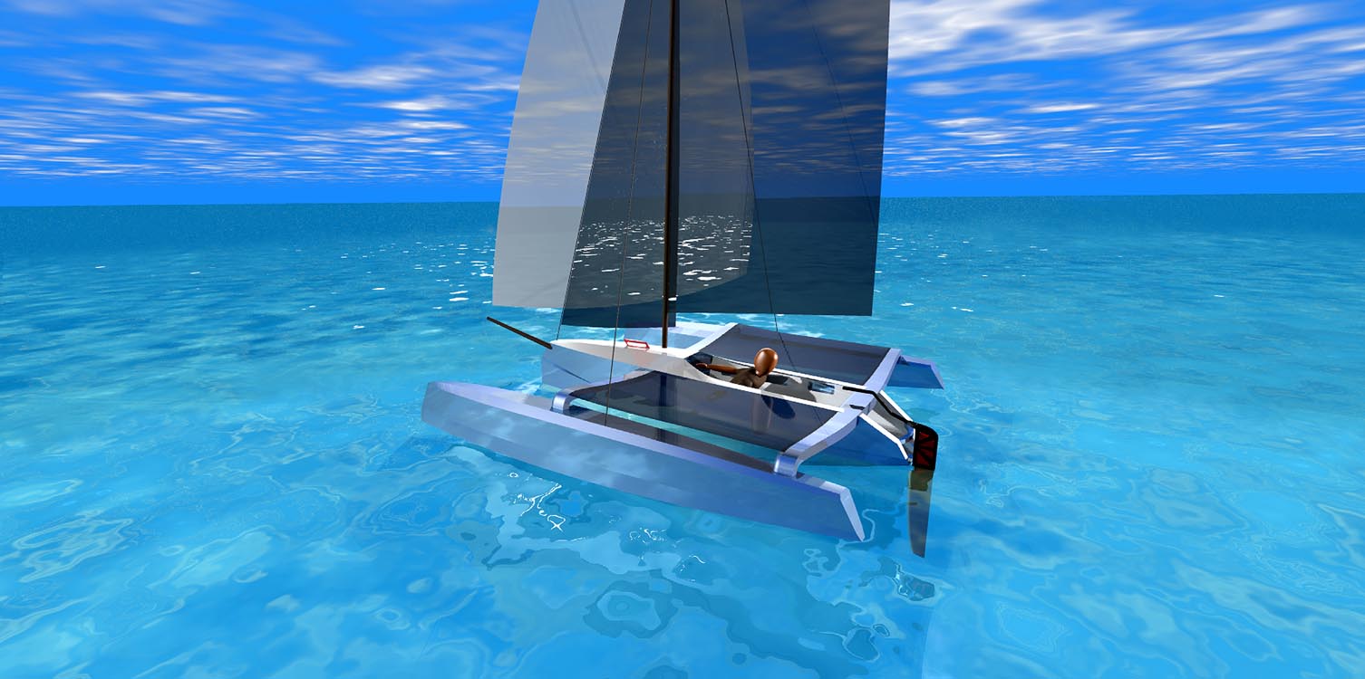
Propulsion to augment the current drift is obtained from a water launchable kite. Naturally, with the kite deployed and providing a 4-5 knot boost to the speed of the prevailing current, the boat will heel in the direction of the kite. To counteract that tendency, the Pencil will deploy a pair of inflatable amas. The amas are shaped like the bulbed keel of a racing yacht to maximize their flow through the water. The Pencil then takes on the wild looking form of a waterborne insect of sorts.

To further enhance the movement of the Oceanic Pencil through the sea an ingenious array of baffle plates are spaced around the cylinder mounted to an elongated oval aluminum tubular frame that is suspended from the upper, above water, reaches of the cylinder.

OP-Folded-High-Tight-w


The baffles are controllable for how they are arrayed. When the baffles are radially oriented around the oval, they reduce the roll of the pencil enormously. When the kite is deployed, the baffles are then moved to fold neatly over one another in the suggested shape of a boat when seen from above. This shape improves the flow of the water around the Pencil hull and at the very narrow end of the elongated oval, the baffles there act as a rudder. If my description is lacking, please refer to the illustrations for better understanding.

The crew has the option to erect a simple set of tubes in pre-positioned sockets so that they may suspend a hammock above the deck of the Pencil in nice weather. I envision long stretches of time in which the weather and seas will be very calm. During those times, the crew can climb out of the Pencil cylinder and virtually live above deck in fresh air and sunlight. He should arrive in England reasonably rested, tanned and fit. This is in stark contrast to the gaunt, near dead apparition that will emerge from the Stasis7 boat from Part One.

I anticipate that a boat of this type, with virtually continuous communication and uplink/downlink capacity, would provide the ideal, long-term research vessel for advanced studies of the sea. This boat should be sponsored by a corporation in the business of communications who wish to be viewed as being at the forefront of technological discovery. With the high visibility footprint of a daily live broadcast to the Internet, this boat could be a floating example of how business can do things to truly benefit mankind as well as inspire young people who are just about to choose science as their filed of study.

I’m thinking someone like T-Mobile would be ideal. Bridge the communication distance between Europe and the United States. Meld ideas and technology into a push to better understand the forces of our planet. Make the Oceanic Pencil the undisputed record holder for the shortest boat to cross a major ocean.

Back Bay Sit On Top Kayak

A Modular System Approach to SOT Kayak Sailing, Paddling and Mirage Drive Propulsion

BB Scorpion bow obl 8 w

Sit-On-Top (SOT) kayaks are easy boats on which to learn to paddle. They have none of the “get in the coffin and you are about to drown” psychological identity that one finds in the Sit-Inside boats and they’re amazingly adaptable to a wide range of paddling activities. It also doesn’t hurt that they are pretty straightforward boats to rotomold, which makes them very cheap to produce in large numbers.

I didn’t envision just one boat for this niche in the home-built kayak market. Instead, it came to me that there would need to be at least three models that could address the wide-ranging styles of boating interests in this area of the kayak world. The result was a couple of very clean, SOT models at 14’ and 16’ called the Corona and the Back Bay, respectively. The third model was going to be called the Wahoo, as it was specifically designed for the folks who spend a lot of time fishing with their SOT’s. I’ll get to the Wahoo in the next article.

As a canoe and kayak sailor and a guy who had just been out for a test drive on the Hobie Adventure Island, which is based on their 16’ SOT Adventure model, I wanted to offer my own take on what makes for a truly fun and stylish, sailing SOT kayak. The result was that a fully integrated system of component parts was designed for the basic Back Bay. This modular approach allows the Back Bay to go sailing by simply adding a system of light-weight, easily built elements that quickly convert the SOT to a single aka sailing boat called the Scorpion, OR, to a double aka sailing boat with slightly larger ama volume, called the Doubloon. Of the two configurations, the Doubloon is most like the well-known and highly respected, Hobie Adventure Island.

The Corona and the Back Bay are virtually identical models, save for their respective lengths. For the purposes of this article, I’ll focus on the Back Bay version and all the potential add-on systems I’ve incorporated in the design.

THE BACK BAY SOT KAYAK

BB16 above w

Specifications:
Length overall – 16′
Beam overall main hull – 28″
Depth of hull max – 12”
Weight – 48 lbs. or less
Displacement – 335 lbs.

This boat is built in the S&G style of construction in 4mm marine ply with 6 oz. plain weave fiberglass set in epoxy on the inside and outside of the hull for full laminate sandwich strength. The build process uses external cradles as building supports, ensuring that the hull goes together with minimum hassle when handling the rather slender and longish hull panels. The boat is bulkheaded internally at three key points. These bulkheads create not only integrated strength in the design, but they also cleanly separate the hull cavity into four unique volumes for gear storage and watertight flotation.

The Back Bay can be configured with a large, open tankwell set aft of the cockpit, or built with a watertight, aft hatch cover for internal storage in a conventional kayak style.

Scorpion bow low w

Specifications:
Beam overall – 10′
Weight (est.) – 90 lbs.
Sail Area – 56 sq. ft.
Displacement – 350 lbs.
Draft (board down) – 28″

The Scorpion variant is a Sit-On-Top design for fun sailing, paddling, or Mirage peddling… or all three, as the builder desires. There will be a design for a leeboard mount included in the plans for those who are going to build the boat for sailing. Having the aka gull wing form set well forward permits a full paddle swing arc.  The aka beam connectives to the amas is split into a pair of mounting elements. I did this to make for a stronger, single beam mounting struture. With a single beam design, there is a tendency for the am to want to rotate around the beam, making for a very stressed component that could lead to early failure. By splitting the beam and spreading the mounting points, I have given the structure more resistance to this rotational force, making for a more rigid boat in use. This setup will allow the owner to power sail in light air with both the paddle and the sail providing thrust. With the leeboard swung down for sailing, the owner can do some “power sailing” and utilize the Mirage drive, as well as the sail, in light conditions. The Mirage is capable of boosting boat speed enough that it creates apparent wind over the sail, adding power where there really isn’t enough for sailing alone.

The amas are positioned to optimize capsize resistance when sailing off the wind. The amas do not touch the surface of the water at rest in stable trim and provide only minimal wetted surface drag when underway by paddle or peddle. As soon as the sail is loaded by the breeze, though, the ama on the lee side begins to immerse, firming-up the boat and resisting the heeling moments being generated.

The aft deck can be configured as a watertight hatch with full access to the aft sections of the hull, OR a large, diving tank well with self-draining ports. The cockpit is fitted with self-drain ports under the seat as well as forward, in addition to the daggerboard slot. There is a watertight deck plate just forward of the seat, between the knees of the sailor/paddler to provide secure storage for critical items that may be needed on a routine basis. The foredeck has a watertight hatch cover for bow storage needs.

The rig is a fully battened Dacron sail with two reef points and a multi-section, self-supporting mast which steps into a sealed mast socket in the hull. The mast and boom sections can be aluminum or carbon, as budget permits. The sail choice is open for the customer as long as it can be balanced with the fixed positions for the mast and dagger board. The Cunningham is run to the deck of the gull wing aka to keep the rig on the boat in the event of a capsize.

With 56-sq. ft. of sail on a 90-pound boat, this will be a decently speedy boat without being in over its head all the time in a stiff breeze. I suggest two reef points in the sail to allow for sailing in a wide variety of conditions.

This will be a wet boat at speed, yet there are no worries at all for flooding and sinking, save for a truly nasty trip over a reef that shreds the entire underside of the craft. The bow, cockpit and aft hull volumes are all independent, sealed compartments, as are the ama volumes.

Reentry from a swimming session will be easy with a simple, sling, or rope ladder much like those used by rock climbers, called etriers.

BB Scorpion aft obl 8 wSliding foot pedals in the cockpit control the rudder. The rudder flips-up when it encounters an underwater obstacle, or when beaching, returning, due to bungee tension to the deployed position once past the obstruction.

The boat is constructed in a multichine, marine plywood style with epoxy glass laminates inside and out in a stitch and glue style. Stainless T-Nuts are embedded in the hull deck surface from below to provide a secure set of mounting points for the aka wing. The amas are held in place on the aka tips by large bungees and a notched lock system. This system provides for quick setups on the beach.

You just fit the aka to the foredeck, insert four, 1/4″ threaded stainless screws with comfortable, knobbed grips and screw down the aka wing. The amas slip onto the ends of the aka and you lift the pair of 3/8″ bungees up and over two raised hooks on the aka ends to secure the ama in place. Simple, easily maintained and near foolproof in operation.

DOUBLOON SAILING SOT

Doubloon bow obl 8 w

The Doubloon is the second variation on the central SOT theme of this group of boats. In this design, I am looking to provide a more expansive utility application for the base, Back Bay SOT version. The Doubloon is essentially a solo craft and it carries the same, 56 sq. ft. sail, but the overall potential of the boat is expanded through the use of dual akas and full trampolines on both sides of the Back Bay hull. The rendering of the Doubloon shows a daggerboard inserted down through the Mirage Drive trunk, but in use, I would prefer to have the board mounted outside the Back Bay hull as a leeboard. Plans will be supplied with the leeboard solution.

The akas on the Doubloon are spaced to allow for a full paddle stroke with the boat setup as a trimaran. There are two sections of tubing that span the opening fore and aft between the akas from which the tramp is mounted. The trampolines are designed to roll-up on the outer tube section, much like a window shade and they are deployed by an endless loop of light halyard line. With the tramps fully deployed, the inner tube section lifts up and over a holding pin in the aka and the sailor applies as much tension to the tramp as he feels he needs by hauling-in the endless loop line and cleating it off. If a paddling session is desired, he simply pops the jam cleat and pulls the line to roll-up the tramp on the outer tube section. This procedure applies for both port and starboard tramps.

Like the Scorpion, the Doubloon can be built to utilize a Mirage drive in the center well and the need to roll-up the tramps for paddling is essentially negated, (though it is nice to have the option once in awhile as Mirage drives can be difficult to maneuver in tight places)

The aka beams are held to the deck of the Back Bay hull with the same, threaded knob strategy for quick setup and takedown times. Similarly, the amas are held to the aka ends with hefty bungee cords for the simplicity of use. There’s another, rather invisible, benefit to using the bungee cords for ama mounting. Because they are being held in place through a fairly dynamic hold-down system, the amas can move about, ever so slightly, while underway. This allows the amas to have some structural “give” and the result is that the banging and thrashing that is typically experienced by the ama, is somewhat dissipated through the flex of the joining system.

Doubloon aft obl wThe design similarities to the Hobie Adventure Island are obvious. This boat, however, should be just a bit faster in the water, mostly because it will be much lighter than the rotomolded Hobie. For that same reason, it will also be easier to put it up on a roof rack for transport to the water and a lot easier on the back when you have to take it off the car to store it at home. The Doubloon configuration allows the sailor/paddler/peddler to bring along extra gear, which can be lashed to the tramps in waterproof bags. They can also take along kids, or perhaps someone special, who could lounge out on the tramp surface while lazily sailing along for a sunset cruise on a warm summer evening.

All in all, I think the Back Bay SOT should be a really fun boat to own for warm water/warm weather boating adventures. It has the capacity to carry enough gear for several days out on the water. When rigged with a sailing system of your choice, it can also cover some pretty good distances if the winds are favorable. Plans for this boat and all its variations will be available from this site and Duckworks Magazine.

Chris Ostlind

Lunada Design
Chris@Wedgesail.com

Blackwater 16

Thin Water Tunnel Hull design

Black Water bow low w

Recently, I put up an informative article on two, economy Jonboats; Swamper and Swamp King: http://lunadadesign.net/swamper-and-swamp-king/ Those boats were drawn to address a very simple and practical approach to a thin water, all-purpose utility skiff and there has been a very nice response from readers seeking plans.

Taking the Jonboat concept further, I got an email from a boating enthusiast asking if I had ever designed a tunnel hull boat along the lines of the Swamper. He indicated that he had seen a boat something like that which had been designed for very thin water work. The boat in question was a full 20’ in length and he felt that the size would be just too much for one guy to either pole around or man- handle in any kind of windy situation. So, he was asking if I had one like that about 16’ long.

It turned out that I did not, but weirdly enough, I had been tossing an idea around very much like his request for some time. He was kind enough to direct me to the www.bateau.com website where I could take a look at the fine design work of Jacques Mertens and his XF20. http://bateau.com/proddetail.php?prod=XF20#.VdpaH_lViko

To be completely candid, I felt that the XF20 was quite a nice boat in every respect except that I had a customer who was asking about one for his needs, which needed to be 4 feet shorter. I had already designed a full-tilt, 18’ vee hulled flats machine for fast runs across open, choppy bays and thin water poling sessions called The Flatsmonster.


Flatsmaster18 Aft Obl w

So, I took many of the ideas I had in the Flatsmonster design and the Swamper series and combined them with the really nice elements of the XF20 to create the Blackwater 16.
Because of this choice of bottom shapes, this boat will be a lot more fun if you try to take it across a choppy body of water at speed. The forward vee shape of the hull will allow for faster speeds in open water as it will help to cut through the waves rather than bounce over them. As a swamper’s poling machine, it will excel in the narrow backwaters and thin mangrove estuaries where some really prize fish hang out, well out of reach of conventional fishing boats.


This is a pocket tunnel hulled boat with a wide stance that can support two fishermen and all their gear in very, very thin water. The hull has defined, 8 degree vee sections up front to help break some of the light chop one might find on backwater sessions in the late afternoon. The run aft from amidships is very nearly flat to allow the boat to plane easily with a very small outboard.

Black Water bow obl above w

If you want to take this boat into the Bayou and hunt for a pig, you’ll find that the hull can carry a very sizeable load with ease. I can really see this design as perfect for a duck hunter. Just rig a short mast in the center of the hull and hang a camo net over the gunnels and you have room to spare underneath for your cooler, your gun selection and the battery powered TV with earphones.

I’m not going to go into the technical description of the pocket tunnel, as there is a wonderful paragraph on the functional aspects on the Bateau site. Needless to say, the tunnel allows the engine to be raised up higher than normal giving additional clearance in the water for the prop to run in shallow water.

Black Water below w

This means you can go further into the creeks in your boat while using the engine. That translates to being able to stay out longer and come home later because of the additional speed over a poled boat in really shallow water. I figure nearly four additional inches of water depth before you’ll have to shut it down and paddle compared to a conventional Jonboat.

I suggest that you don’t exceed 30 hp for an outboard on this boat so that you can maximize the potential of the thin water capability. It’ll run surprisingly good with a 10-20-hp engine and in thin water and tight quarters, a lot of power would just go to waste, anyway. There’s a tendency to install too big an outboard on most recreational boats. I’m hoping that most folks recognize that a lighter, more efficient engine is actually better all around for 90% of all the boating work you will need to do.

Black Water structure w

Construction of the boat is in stitch and glue style with 3/8” hull bottom panels, deck, seat and fishing surfaces and ¼” plywood everywhere else save the transom. There is a lightweight framework truss in the hull beneath the deck to give the boat longitudinal strength. The suggested bench seats and forward fishing platform also serve as flotation chambers to keep the boat afloat in case it is swamped. The builders of this boat have the potential to build the interior out anyway they would like beyond the supplied bench seat design, but the more they add, the heavier the boat gets and that starts to take away the thin water capability of the design.

As shown in the illustrations, there is a midships frame and a continuous surface deck. Under the deck are two, full length stringers. These additions provide for a near bullet-proof hull with an added benefit. If the hull skin were to be holed from an unseen underwater obstacle, the flooding would be confined to the area of the damage as the compartments under the deck are sealed from one another to provide flotation integrity. Yes, the boat is a little heavier, but the payoff is in the enhanced safety, and hull rigidity if you decide to take it up to faster planing speeds.

Black Water aft obl wThis is an easy boat to build and it will provide hundreds of hours of enjoyment for the owner, especially after he customizes the interior to suit his favorite applications and fits-out the boat with all the trick goodies for his recreational passion.I suggest that the boat be built with epoxy taped seams inside at all joints with a full layer of epoxy glass on the outside of the hull. Prudent builders will add a layer (or two) of extra glass at all the sharper, hard corners to protect them from the inevitable banging a boat of this type will receive during use.

Plans will be available in the next month from Duckworks and will run USD$75. They include full-sized paper templates and detailed instructions regarding any of the stuff that is not straight forward, simple. There is also a suggested layout map for nesting the panels efficiently. The templates allow you to simply scarf together the ends of the full sheets of plywood, layout the templates, trace a line around the edges and start cutting the hull panels. No lofting required and quite a bit of time saved plotting points and bending sticks.

Chris Ostlind
Lunada Design
Chris@Wedgesail.com

Lunada Bay Double Sea Kayak

18’ compact double sea kayak

Some time back, Fred Gasper, from Haslett, Michigan, and I exchanged a few emails about a boat project he wanted to undertake. He was looking to build a double sea kayak so that he and his wife, Kathy, could enjoy paddling activities together. Fred indicated that he had already built several plywood kayaks and was just about finished with his second stripper canoe, so I knew he would not need an extensive guide through the basics of building a larger boat for he and his gal.

Duckworks Magazine

You can see in the accompanying photo that Fred has pretty well mastered the art of fine woodworking when it comes to building boats. As a new designer with several boats of my own out in the world, I was looking to get connected to another builder who had the talent and the experience to produce a terrific finished boat. Clearly, after taking a look at some of Fred’s prior projects, I was excited to be combining efforts with his capability.

Duckworks Magazine

Fred and Kathy have quite a bit of experience when it comes to taking kayak oriented journeys. They’ve made a few trips to the Pacific Northwest to do just that. They both have a well-developed understanding of what a boat is supposed to do when paddled.

I developed the Lunada Bay design to fill a special niche in the double touring kayak market. The design brief addressed such things as being car-toppable, easily stored in the average garage or basement, able to carry two adults for day paddling and the odd overnighter, highly responsive to turning input and able to track effortlessly. The boat did not need to be able to carry a week’s worth of gear and food or produce a high, sustained speed under paddle, as it was to be a comfortable cruiser for more leisurely outings.

The result was an asymmetric hull design of 18’ LOA with a beam of 28” to be built in a hybrid construction method. Hybrid build style is basically the combination of a marine plywood, multichine hull with a cedar strip built deck. This type of boat takes advantage of the two build styles to offer quick hull construction combined with the natural wood beauty of a stripped deck. It also allows the soft sweeping contours of a stripper on the part of the boat that is most often seen by the paddlers.

In this style, the builder first assembles the hull panels, fillets the hull seams and glass laminates the hull inside and out. He then inserts a series of building stations for the stripped deck process and begins to create the patterns as desired with various colors and species of wood to suit his taste. The hull, itself, provides the strongback form for the stations and soon, the deck is complete and ready to join to the hull with the bulkheads in place.

The cockpit openings are laid-out on the deck surface taking care to measure the Center of Buoyancy of the design to balance the paddling positions in the boat. Once cut out, the cockpits are finished with the construction of the rims and flanges for the paddling sprayskirts. There are probably five recognized methods for cockpit rim fabrication. All of them work and it more or less comes down to how you want the whole thing to look. Something like choosing plaid instead of print for a shirt pattern.

Just last week, Fred and Kathy took their new boat out for a spin on the local lake to see how she’d perform. Fred had been working on the boat, off and on, since mid February. He managed to squeeze-in a trip to the Grand Canyon with Kathy, family obligations, the normal household chores, as well as his regular job, all at the same time. He was more than ready to get the boat on the water. The coming change in the weather probably played an additional role in the urge to go paddling.

Duckworks Magazine

I’m pleased to share with you that the boat performed like a star, ticking off the big elements in the design brief while being put through her paces by Fred and Kathy on an overcast, October day in Michigan. Fred just sent me an email and said, “Tracked and turned great with no weathercocking. Don’t think she will need a rudder. We named her “Travelin’ Louise”

This kind of report is pure music to a designer’s ears. I jumped-up from Fred’s email and took my wife and son out to dinner to celebrate. Everything was great, except my wife wouldn’t let me eat the greasy, garlic mushroom burger I really wanted to order. Seems that even though I can design some really nice, trim boats, I have a long way to go to get my own hull form back to my former nice lines.

Fred and Kathy will need to install the backbands, footbraces, carry straps, seats, deck accessories and then finish off Louise with several coats of beautiful, satin varnish before they put her away for the winter. Fred indicates that the finished boat will tip the scales at just over 60 pounds. I’m really looking forward to the reports from their future adventures in “Louise” over the coming years.

Duckworks Magazine

As an aside, the name Lunada Bay comes from a local surf and snorkeling location from my youth along the beaches of L.A’s South Bay. Where I come from, Lunada is a Spanish word that loosely translates to a moon lit party on the beach. I have spent many warm summer evenings with friends, cooking freshly caught lobsters and abalone on the beach while a full moon lit the sea. I couldn’t think of a better way to use this boat.

Chris Ostlind
Lunada Design

Chris@Wedgesail.com


Swamper and Swamp King

A Superior Weapon for the Outdoorsman


Swamper King & Swamper

One day I was driving around the industrial area near my boat shop and happened to pass the local power boat center. Sitting out front of the store were two, rather homely looking aluminum skiffs that are typically used around Utah to hunt ducks and geese and perform general boating duties for outdoorsmen.

I had never really taken a good look at the type before as I had more pressing matters in front of me trying to finish the build on a sailboat. For some reason, I pulled over to just get an idea as to how these metal boats went together and to understand the shapes that went into the hull. Most folks refer to the form as a Jonboat, although I’ve also seen it as Johnsboat and Flat-Bottomed Skiff, by various other sources.

Jim Michalak’s version of this simple skiff has been a real hit with homebuilders and there’s a bunch of good reasons why that’s so. They’re easy to build, provide hours of trouble free operation with the simplest of outboards and can do just about anything you could ask for a utility boat.

I went home that night and dialed-up the design software and started fooling around with a few ideas as to how I would design one of these boats for my portfolio. The result is that I came up with two versions that are very much alike except that one is a bit longer than the other for added carrying capacity is.

Swamper

Swamper 15 bow obl wThis boat is designed to take advantage of the physical properties of the standard, 4×8’ sheet of plywood and make the most of the sheet goods while still imparting a bit of style and form enhancement to the hull shape.

Rather than design a straight, flat-bottomed hull, I chose to give the Swamper a very slight Vee shape for the underwater parts. This gives a somewhat better ride through choppy conditions such as those you would find on any small lake when the wind comes up. If you’ve ever ridden in a flat bottom hull while pushing through small waves and experienced the slamming effect that comes with a flat surface as it hits the oncoming wave, you already know what I mean by this.

The overall length of the boat is 15’5” and the overall beam is just a shade over 55”. The height is 22” along the sides with the gunnel rising from that height in a soft curve, yielding a bow that is only 28.5” above the floor of the boat.

The main components come out of seven total sheets of plywood. The two bottom panels are from 3/8” material and the rest of the boat is from ¼” stock with the exception of the transom which is built from two layers of 3/8” ply. The boat is epoxy filleted and taped on the inside and completely covered in epoxy glass on the outside surfaces. The build style is simple, stitch and glue with one butt joint connection to be made to get the full-length hull panels.

There is a full-length stringer at gunnel level and it is covered with a four-inch wide cap rail completely around the boat with the exception of the transom mounting location for the engine.

Swamper 15 aft obl wBuilt-in flotation chambers are installed throughout the hull, starting with a big standing platform in the bow that is suitable for fishing. The forward seat can be enclosed with watertight bulkheads as is the far aft seat platform. Two enclosed flotation boxes sit on either side of the engine splashwell. You can swamp this boat and it will not sink.

The flotation chambers can be easily adapted to provide on-board storage if the builder installs watertight hatches or inspection ports.

I feel that the optimal, outboard engine size for this boat would be in the 15-20HP range. It will work just fine with a smaller engine, though, as the boat is quite light. I’m sure somebody will hang something bigger than this, but I’m not recommending it.

Swamper 15 above w

The Swamper is perfect for fishing; hunting work related tasks on the water and just plain old fooling around. It can go into some pretty thin water with its draft of just under 7” at 650 pounds of displacement and can easily be setup with oars and a removable center seat for human powered applications.

If you live out in the country and have a good relationship with the local Sheriff, the Swamper will fit snugly between the wheel wells of the standard American pickup. With the tailgate down, you’ll have five feet of boat hanging out, but it is doable. Again, I’m not recommending the practice; just letting you know it can be done… if you’re so inclined.

Normal transport would be with a lightweight trailer, which would allow you to keep the outboard on the boat for short distances. A 15 Hp outboard doesn’t weight too much, but I prefer to see them removed from the transom for transport over long distances.


Swamp KingSwamper-Swamp King Comparison w

This boat is very much like the Swamper with virtually the same lines. The biggest differences are the length at 18’, the ability of the boat to carry more weight and the addition of an extra, installed seat with its enclosed flotation volume. With an extra layer of ¼” plywood on the transom, this boat can easily handle a 30-40 HP motor.

The costs to build the Swamp King are slightly greater due to the added plywood for the increased length and some additional trim, structural material as well as extra epoxy and glass.

Swamper-Swamp King Comp Bow w

Even though these are simple boats, they are capable of providing years of wonderful service to the owner/builder with only very minor maintenance. If you have a teenage son or daughter who likes to enjoy outdoor activities with you, this boat would make for a terrific joint project over the winter. Either the Swamper or the Swamp King would make an excellent first boat to hand down when one of them gets old enough to have a boat of their own.


Big Horn Solo Canoe

SOLO TRIPPING IN A VERY RESPONSIVE PACKAGE

Big Horn Bow w

Right up front, I’m going to give a full tip o’ the cap to John Winters, Canadian boat designer, for the inspiration to design this particular canoe. John’s Osprey II S&G design is a beautiful example of a designer bringing his enormous, gifted skills to the worktable. I wanted to draw a solo, tripping style canoe for 4mm marine plywood construction, so I took a long look at the Osprey to see if there was anything I could do differently with the form.

Note: At the end of this article, there is a report from a builder and the results of a committed journey with the Big Horn in the Boundary Waters Canoe Area. Please continue reading to discover a first-hand report as to how the boat behaves in the real world. From a designer’s perspective, it is incredibly satisfying to have independent verification of all the hours that go into the design of a boat like this one.

In Winters’ design, there is a very nice, tumblehome chine along the shear to give additional paddle stroke clearance. I have built boats before that used a similar tumblehome panel and it turns out that they can give the builder some interesting problems when it comes to constructing the hull.

This tumblehome chine is very slender in width, which requires the builder to have a reasonable set of skills to wire it in place prior to filleting or they will end-up with a potentially wavy hull section that just won’t go away short of doing it over. Since I was looking to draw the Bighorn for easier construction for the average guy, I decided to drop the tumblehome panel and instead raise the outer hull panel to maintain freeboard. The result is a six panel hull that is easy to build and nice looking.

Specifications
Length – 15′
Width – 30″
Draft @ 280 lbs. – 3.8″
Weight (estimated) – 42 lbs. (Actual weight 38 lbs.)
Rocker-bow – 2.3″
Rocker-stern – 1.8″


Big Horn Aft wThe hull shape is asymmetric in form with the widest point (and it’s center of buoyancy) just aft of the hulls’ midpoint. The hull also has decidedly enhanced rocker fore and aft when compared to traditional canoes of this size. These two design features give the boat very solid, straight-line tracking, as well as wonderful response to turning stroke input from the paddler.

At full, 350-lb. displacement load, the Bighorn has just less than 8” of freeboard amidships. I don’t see this kind of load in this boat unless the owner is going out for a very long solo trip and needs to carry a lot of gear. More likely, you’ll be seeing an all-up, ready for trouble, load of around 290-300 pounds, depending on the weight of the paddler. I figure this boat can be built at right around 42 pounds, providing the guy with the resin doesn’t get too generous with the glue.

Big Horn Above w

The seat setup in the renderings illustrates my take on an integrated unit recognizing the typical canoeists needs when out paddling. There’s a comfortable, sculptural sitting area much like the tractor-style seats one sees on the Wenonah canoes. It is coupled with an integrated pocket on one side for camera/binocular/etc. and on the other side… a circular, net bottomed opening to hold the beverage of your choice. (Ever had a can of coke tip over in your canoe while paddling because there was nowhere secure to hold it? Makes for a fun clean-up session, doesn’t it?)

If you don’t care for the integrated seating system, you can always use the traditional, woven caned seat, a simple, stretched canvas platform or a woven-webbing seat. For that matter, you could always buy a tractor seat from Wenonah.

Outside the typical description of a solo canoe introduction, I decided to include a little extra teaser for those so inclined. I drew a set of outriggers specifically for this boat.

Big Horn with Small Amas w

They aren’t fancy in appearance, but they are very simple to build, easy to use and they provide enormous stability to the boat if you’d like to fish, shoot pictures, take a nap, shoot birds, etc. If you were so inclined, they can also be used with a modest sail rig to allow the Bighorn to be sailed like a trimaran, though don’t be expecting these amas, or the suggested sail rig size of 30 sq. ft., to provide much more than a pleasant sailing experience. Still, it could be fun on the right body of water.

Water Test Report by Stan Heeres

Sunrise-on-the-Boundary-Waters

Build process documented along with the first trips out on the Boundary Waters Canoe Area

The complete web record of the Heres build is currently not available. I’ll search for it and locate what I can of the document.


Stan Heeres’ recent comments as follows:

“I purchased plans from you for the Big horn a few years ago. My son and I built the canoe and have since been on 2 Boundary Waters trips with it.
I promised you that I would detail the building process. I did and am just finishing the presentation up and will post it soon.
I have also built the John Winters Osprey (both the strip version and the plywood version). Here are a few details”

Strip Osprey

Lightest(34 lbs), receives the most comments by a wide margin (it looks really good), slowest of the 3 and hardest to keep in a straight line of the 3 at speed.

Plywood Osprey

2nd lightest lightest(36 lbs), very functional but does not get the comments, 2nd fastest and stays in a good straight line.

Big Horn

Heaviest(38 lbs), glides like a dream, Kevin, who uses it, will effortlessly pull away from the other canoes, tracks straight as an arrow.

Cherokee-Morning


It’s pretty clear that I am proud of the boat and how it has turned-out for an experienced canoe builder. Being able to say that one of my boats can effortlessly pull away from a design created by a known master in the trade is exciting. That it also has terrific tracking manners when loaded and out on serious water, really makes all the design considerations worthwhile. Stan, thanks so much for the really kind words on the boat. I’m really looking forward to Kevin’s report.

Solo 12 and 14


I have developed a new, personal trimaran for small adults and kids called the Solo12. This is a car toppable boat that is meant to sail with no facility for human power other than hauling out the spare canoe paddle and getting with it. The total displacement is 300 lbs. all-up and should tip the scales at about 130 lbs. before getting wet. So, there’s room to wiggle for a wiry dude who wants to tool around in quiet waters and have a blast in a semi-reclining position. Steering is via a pair of pedals and cables to the rudder cheek block, much like a kayak and all the sail controls are fed forward so there’s no need to hike out at all.

The sail area is 56 sq ft. The amas are generously sized to avoid getting out of the cockpit except to hang-out on the beach with friends and have some lunch. Lateral resistance will be provided by a side mounted leeboard on a swivel mount. This will give the boat plenty of upwind lift while being a safety oriented feature that kicks up and out of the way for beaching, or encountering underwater obstacles

The aka tubes are aircraft aluminum and will be segmented with the same spring pins and fitted ferrules you see on take-a-part paddles, so that the amas will reconnect right up next to the main hull for transport and storage. A very compact unit for putting on the roof of your car and going off to the beach, or lake, for some fun.

The build is 3mm marine ply with a full layer of glass outside and taped joints inside. Easy to build, easy to move around the launch site and perfect for learning to sail with little kids as they can sit between your legs and learn how things work. Later, the same kids can take the boat out on their own and there will be no fear of them tipping over unless a tornado hits the area.

There is a companion model at 14′ LOA for slightly larger sailors, all within the car-topping attitude that this boat represents. The SOLO 14 has an optional ama design that allows the removal of the leeboard as the lateral resistance will come from the underwater fin shapes of the amas. This keeps the stuff hanging in the water to a minimum while still allowing a decent performance capability. fewer moving parts will mean simpler maintenance and less stuff to possibly break while out sailing. The rendering above shows the finned amas in place.

Chris Ostlind
Lunada Design
Chris@Wedgesail.com

Rocky Point Sea Kayak

Rocky Point-lunada_bay

I grew up just a couple of miles from the Palos Verdes Peninsula along the coast of Los Angeles County and would often snorkel in those waters for abalone and lobsters with a group of my friends. One of the first “boats” I ever worked on, a leaky, 12′ paddleboard rescued from the heap out behind the main Lifeguard station in Redondo Beach, was used to explore the area with my buddies. Later, we cobbled together a catamaran of our own making by screwing together two of the paddleboards down on the beach and paddling both of them out to our favorite dive and play area.Guarding the northernmost entrance to Lunada Bay is Rocky Point. The waters around Rocky Point, which is the northern limit of the famous big wave riding area known as Lunada Bay, can be anything from totally benign and calm, to a full tilt, out of control melee of oceanic surges and thundering waves. When I started to design boats, I instinctively drew upon locations from my boyhood watery exploits and the name for this sea kayak, Rocky Point, came from this familiarity.

The Rocky Point is designed as a very fast, no-nonsense expedition touring boat with the capacity to carry the necessary gear and stores for an extended stay away from civilization. Obviously, with its narrow beam, this is not a beginner’s boat. Experienced paddlers, though, will settle-in quickly to its gently lessened stability and be able to make the most of the very small frontal area and very long waterline.

The prismatic coefficient of the hull is set to .55 which will allow the paddler to reach and hold a very fast cruising speed. The boat should be equipped with an expedition class rudder to provide a gentle assist in turning as the hull has reduced rocker from my other sea kayak designs and turning was considered a skill for the advanced paddler for whom the boat was created..

Length Overall
18′ 6″
Beam Overall
20″
Length at Waterline
18′ 5″
Beam at Waterline
19″
Displacement
300 lbs. at design waterline

Chris Ostlind
Lunada Design
Chris@Wedgesail.com


Driving Sodebo w

‘Diamonds from the sky’

VERY interesting news from the scientific community just yesterday with the announcement of a technique to create carbon nano-fibers right out of the atmosphere to be used for a wide collection of applications, including the structural elements for boats.

carbon-nanotubes-atmosphere

‘Diamonds from the sky’ approach turns CO2 into valuable products


BOSTON, Aug. 19, 2015 — Finding a technology to shift carbon dioxide (CO2), the most abundant anthropogenic greenhouse gas, from a climate change problem to a valuable commodity has long been a dream of many scientists and government officials. Now, a team of chemists says they have developed a technology to economically convert atmospheric CO2 directly into highly valued carbon nanofibers for industrial and consumer products.

The team will present brand-new research on this new CO2 capture and utilization technology at the 250th National Meeting & Exposition of the American Chemical Society (ACS). ACS is the world’s largest scientific society. The national meeting, which takes place here through Thursday, features more than 9,000 presentations on a wide range of science topics.

1439986093313

“We have found a way to use atmospheric CO2 to produce high-yield carbon nanofibers,” says Stuart Licht, Ph.D., who leads a research team at George Washington University. “Such nanofibers are used to make strong carbon composites, such as those used in the Boeing Dreamliner, as well as in high-end sports equipment, wind turbine blades and a host of other products.”

Previously, the researchers had made fertilizer and cement without emitting CO2, which they reported. Now, the team, which includes postdoctoral fellow Jiawen Ren, Ph.D., and graduate student Jessica Stuart, says their research could shift CO2 from a global-warming problem to a feed stock for the manufacture of in-demand carbon nanofibers.

Licht calls his approach “diamonds from the sky.” That refers to carbon being the material that diamonds are made of, and also hints at the high value of the products, such as the carbon nanofibers that can be made from atmospheric carbon and oxygen.

Because of its efficiency, this low-energy process can be run using only a few volts of electricity, sunlight and a whole lot of carbon dioxide. At its root, the system uses electrolytic syntheses to make the nanofibers. CO2 is broken down in a high-temperature electrolytic bath of molten carbonates at 1,380 degrees F (750 degrees C). Atmospheric air is added to an electrolytic cell. Once there, the CO2 dissolves when subjected to the heat and direct current through electrodes of nickel and steel. The carbon nanofibers build up on the steel electrode, where they can be removed, Licht says.

To power the syntheses, heat and electricity are produced through a hybrid and extremely efficient concentrating solar-energy system. The system focuses the sun’s rays on a photovoltaic solar cell to generate electricity and on a second system to generate heat and thermal energy, which raises the temperature of the electrolytic cell.

Licht estimates electrical energy costs of this “solar thermal electrochemical process” to be around $1,000 per ton of carbon nanofiber product, which means the cost of running the system is hundreds of times less than the value of product output.

“We calculate that with a physical area less than 10 percent the size of the Sahara Desert, our process could remove enough CO2 to decrease atmospheric levels to those of the pre-industrial revolution within 10 years,” he says.

At this time, the system is experimental, and Licht’s biggest challenge will be to ramp up the process and gain experience to make consistently sized nanofibers. “We are scaling up quickly,” he adds, “and soon should be in range of making tens of grams of nanofibers an hour.”

Licht explains that one advance the group has recently achieved is the ability to synthesize carbon fibers using even less energy than when the process was initially developed. “Carbon nanofiber growth can occur at less than 1 volt at 750 degrees C, which, for example, is much less than the 3-5 volts used in the 1,000 degree C industrial formation of aluminum,” he says.

http://www.acs.org/content/acs/en/pressroom/newsreleases/2015/august/co2.html


CORSICA 15R

Sports Car Performance on the Water


Over the past couple of years, I have taken a break from my boat design work. During that time, I’ve been able to reassess my connection to the craft. The last boat I designed was the Europa 20, which is a trimaran meant for vertical strip foam construction with sandwich style, infused epoxy/glass laminates inside and out. The Europa is a boat for very fast day sailing with a very light hull and a very big rig. A boat that is not for everyone, to be sure, as it requires a level of skill that the average guy does not typically cultivate in the course of experiencing their recreational boating interests.

In stepping away from the larger, more powerful beach type multihulls, I came around to the desire to produce a smaller, very quick and sensitive boat that would appeal to recreational sailors and not just those guys who want to blast around with their hair on fire (though I do suspect that in the right hands, this boat will do just that). The new design had to be easy to build with standard, marine plywood/epoxy/glass techniques that did not rely on exotic layups with spendy carbon cloth. (Well, maybe the carbon will sneak in there a bit on the beams for the guys who want to play with a bigger rig)

Looking long and hard at the smaller skiff-like hull designs I had done before, such as the Montage, I decided to draw the new boat in that same general size, but with a very different approach when it comes to how the boat achieves its performance potential. Where the Montage has a relatively spacious cockpit capable of taking on a couple of adults, (or a parent and a couple of smaller kids) the new, Corsica 15R trimaran would be for one adult (or accomplished kid) designed solely for a unique, one-up sailing experience within the small beach multihull genre.

Corsica15R bow high water wMuch like a performance dinghy, the Montage has a wide, flat sailing surface conducive to the planing of the main hull. It’s more like an outrigger supported dinghy in that regard, than it is a trimaran. Certainly, the Montage fits within a grey area when it comes to defining nomenclature. The Corsica 15R, however, would be very much like other high performance trimarans with very slender, easily driven hulls that have the potential to achieve boat speeds well beyond the typical displacement design. There is no main hull planing function going on with the Corsica 15R. It is all about pure, straightforward achievable speed via well-known multihull design thinking.

As a result, the boat has minimized clutter when it comes to excessive high-tech trickery. With that approach, the Corsica 15R is also going to be a boat that has much lower maintenance requirements in order to keep it in top sailing condition, as well as a much lower realized cost to get it on the water and ready to sail.

If you are into cars, as I am, then think in terms of a nicely pumped, Mazda Miata, type of boat that would be a cool, weekend canyon racer for one person. A boat that could blast around the local waters in a good breeze and give chase to other small, fast, multihulls being sailed by crews of two.

The result of this conceptualizing process is the Corsica 15R. The C15R is a boat of modest, marine plywood build techniques and is very light weight for its generous sail area. With this boat, the normal sailing position would be the skipper, semi-reclined within the main hull, driving his machine like an F1 Grand Prix car. In this configuration, the boat is designed to utilize foot pedals for steering, leaving the hands free to work the sheets. But, that’s not the only way to sail this boat. Owners who wish to sail in a more conventional multihull style, can sit-up out of the cockpit and onto the main hull cockpit gunnel, or even the trampoline surfaces all the way out to the ama, where they will steer with a tiller extension.

Corsica15R above w

A construction style in multichine, 4 mm marine plywood, allows the boat to be assembled in a well-understood fashion that will go together quickly. With a subtle placement of minimal stringers and sufficient bulkheads, the C15R becomes a strong main hull shell that can absorb the loads from its sizeable rig, turning the power of the sails into forward thrust in the water.

There is no fully enclosed transom on the vaka hull. The cockpit deck is slanted gently down and aft for automatic self-draining, such as is seen in sport dinghies and larger race boats. A collection of bulkheads under the cockpit deck provide structural support and watertight compartments ensuring that the boat will not likely sink even if large sections of the bottom are torn out from an underwater hazard while smoking along in a gin clear lagoon.

The demounted boat can be assembled easily by one person. The gently gull-winged akas are built with a glassed box beam core.  The inboard ends of the akas slide into tapered sockets in the main hull and are levered in place with stainless waterstays to make ready for sailing. This, tapered socket technique prevents binding while assembling the boat, while providing a solid, hassle-free and weight minimized demounting system. The leading edges of the akas are smoothly shaped foam blocks that are glassed onto the box beam to provide an aero component, as well as creating reduced drag from waves and spray. The akas are hard fastened to the amas as a complete assembly that is easily removable from the vaka hull. The trampolines stay mounted to the akas and amas for transport and only have to be hooked and tensioned to the main hull during assembly.

The mast is a stick from a Hobie 16. I specify the addition of a set of spreaders from the Hobie 18 mast to stiffen up the H16 mast to handle the additional righting moment generated by the Corsica design. Naturally, I’d prefer to see fresh sails in something like fully battened, Pentex laminate, but builders on a tight budget could also work with a loft service to tweak a reasonably fresh Hobie 16 main and jib and do just fine. The addition of reefing points on the main are strongly suggested, as well as the use of furlers for the jib and spinnaker/screacher. For those who desire fresh sails for this boat, I would recommend the folks at Whirlwind sails in San Diego, California. http://www.whirlwindsails.com/

Corsica15R bow water w

A removable carbon prodder sets the tone at the front end of the boat. The stick originates as a carbon windsurf mast, so it is easily found on the used market and equally replaceable, should it get poked into an unyielding environment. For trailering, the sprit unpins, slides out of its socket and is stowed in the cockpit for transport and storage.

Corsica 15R Specifcations

LOA                                         14’ 11”  (4.54 m)

BOA                                         13’  (3.96 m)

Displacement                         650 lbs.  (294.8 kg.)

Sail Area (upwind)                 218 sq. ft.  (16.17 sq. m)


Spin                                       142 sq. ft.  (13.19 sq. m)

Mast Length                           26’  (7.62 m)

Draft (board up)                     1’  (.3 m)

Draft (board down)                42” (1.07 m)

The mast is raised by the traditional beach cat method of physically lifting the mast with the base pinned to the mast step, or by utilizing the long daggerboard in its trunk as a form of a gin pole. A forward hoisting line is led over a pair of sheaves at the top of the daggerboard and down to the hand cranked winch on the trailer. Mechanical leverage quickly raises the mast so that the forestay can be fastened to the bow, stepping the mast securely. You can see a few photos of the process at Brent’s L7 trimaran site:

http://home.comcast.net/~ritakend/site/?/page/Mast_Raising/&PHPSESSID=864f3404e3f46ed29dd99b863018fc1d  This is a very simple way to raise a mast should you need to avoid the trad lifting exercise for one reason or another.

I chose to not go with tricked-out, curved lifting foils in the amas due to construction complexity and added cost for the builder. Foils of this type are hard to build correctly by hand, as are the needed curved trunks in which they slide. Instead, the boat is equipped with a daggerboard that is inserted through the deck of the main hull in front of the mast which angles aft to exit the hull below the waterline. A daggerboard and trunk of this type are much simpler forms to build and orient in the hull. It is also just one main foil, where lifting foils need to be made in pairs, one for each ama. Lifting foils also need complex control mechanisms to retract and deploy the foils and they have to work from the cockpit remotely with the foils mounted way out in the amas. The needed controls are an interesting problem when the boat is 13’ in width and the driver is semi-reclined in the main hull.

Note: I’m not against an owner who might want to experiment with foiling for this boat, even if it is just foil assist and not full flying. It would require a lifting t-foil style rudder and twin Bruce style foils in the amas, or, if a person is really accomplished as a composites builder, they could make a pair of matching c-foils for the ama. The owner just needs to know what level of additional work is involved and at what skill level they need to perform in order to get the desired result.

Corsica15R beam water w

If you are on a budget, the rudder and headstock from a Hobie 16 will work just fine for the Corsica with some mods to the tiller. The more deluxe, Rudder 25 system from Dotan will also work well, should you have the coin.  http://www.dotan.com/  If you plan on pushing the boat hard, then a longer blade will be required, or you can get yourself invested in the process of putting a rudder on each ama and have stunning control at your finger tips. On the down side, that change will cost you a bit out of your pocket and at the launch ramp in setup time… though I can see a nifty rig with light alu tubing and the use of snap buttons as a cool solution.

The Corsica 15R will be a light boat built from familiar materials. It should be a fairly simple building experience for the owner and will fit comfortably into any typical garage space, making it easy to find a building location. It will quickly assemble for sailing and be hassle free with minimal maintenance required to keep it in top form. It can be towed behind any compact car on a typical beach cat trailer and when demounted for travel, is road legal anywhere in the world. On the water, this boat should be quite quick and behave with predictable, pin-point sailing manners. With the skipper slung comfortably in his reclined cockpit seat, he will be decently protected from the effects of the weather and sea state while tearing around his local waters.

Chris Ostlind

Lunada Design